
Translation note: This article was translated with the assistance of AI.
Aircraft propulsion starts with a simple requirement: produce enough thrust to overcome drag and move the aircraft through the air. In modern commercial aviation, that task is performed almost exclusively by the turbofan engine.
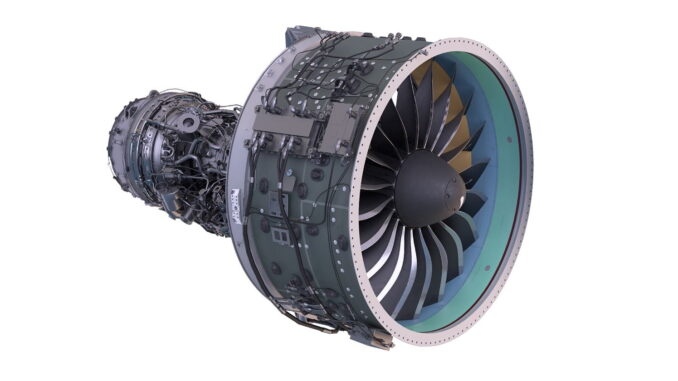
Behind the large fan visible at the front of the nacelle is a much more complex system. Compressors raise the pressure of incoming air, fuel is burned in the combustor, turbines extract energy from the hot gas stream, and concentric shafts transfer mechanical power through the engine.
The underlying gas-turbine principle has remained recognizable for decades. What has changed dramatically is how efficiently individual modules operate together, how high pressure and temperature levels can become, and how much air can be accelerated for a given amount of fuel.
A useful technical introduction to the basic architecture is provided by NASA’s turbofan overview.
From inlet to nozzle
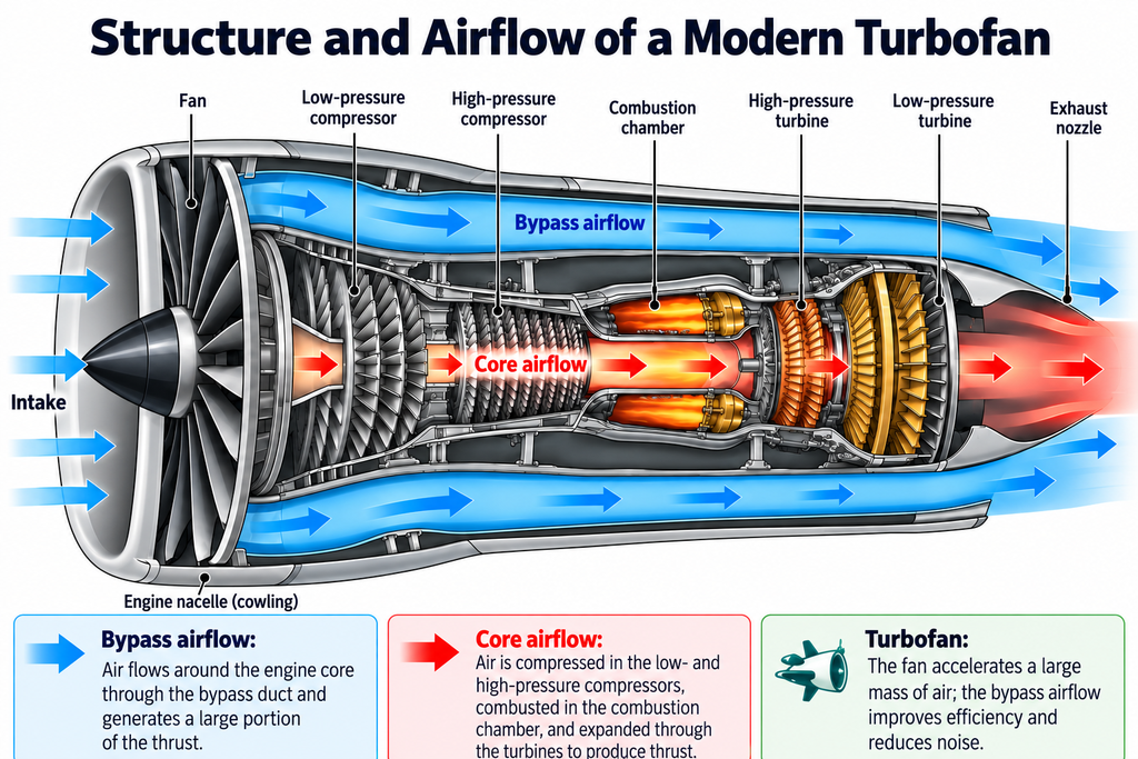
Air first enters through the inlet and reaches the fan.
Behind the fan, a turbofan divides the airflow into two paths. The core flow passes through the gas generator. The bypass flow travels around the core through the annular bypass duct.
The core consists primarily of compressors, a combustor and turbines. Depending on the engine architecture, these modules may be divided into low-, intermediate- and high-pressure systems rotating on separate concentric shafts.
The basic process can be summarized as:
intake – compression – combustion – expansion – exhaust.
The turbine plays a crucial role because it does more than extract energy from the hot gases. It provides the shaft power required to drive the compressor and fan.
The fan moves most of the air
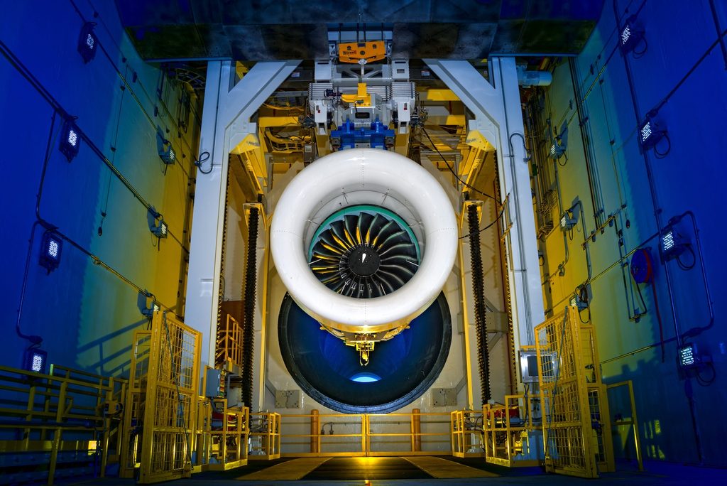
The fan is the large first rotating stage of a modern civil turbofan.
In a high-bypass engine, most of the incoming air does not pass through the combustor. Instead, it flows around the core.
The ratio between bypass mass flow and core mass flow is known as the bypass ratio. NASA defines it as the ratio between fan or bypass mass flow and core mass flow.
A bypass ratio of 10:1 means that roughly ten units of air pass around the core for every unit passing through it.
This matters because propulsive efficiency generally benefits from accelerating a larger mass of air by a smaller velocity increment rather than accelerating a smaller mass to a much higher velocity.
That principle has driven the development of increasingly large fans.
One example is the Pratt & Whitney GTF.
Compressors raise the pressure
Air entering the core passes through the compressor system.
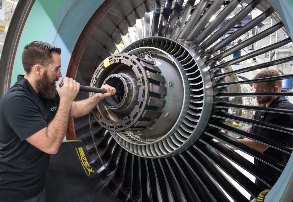
Most large modern engines use axial compressors. Air therefore moves predominantly along the engine axis through alternating rows of rotating and stationary airfoils.
The rotor adds energy to the flow. The following stator redirects the air and contributes to pressure recovery before the next stage.
Modern turbofans normally divide the compression process between at least two systems: a low-pressure compressor and a high-pressure compressor.
This division allows different parts of the engine to rotate at different speeds.
The high-pressure compressor is one of the most highly engineered modules in the engine, with tight clearances, multiple stages and significant aerodynamic loading.
Combustion adds heat to the cycle
After compression, air enters the combustor.
Fuel is injected and burned continuously. Unlike a piston engine, a gas turbine does not perform intake, compression, combustion and exhaust sequentially in the same chamber. These processes occur continuously in different parts of the engine.
The combustor must maintain stable combustion over a wide operating range while limiting pressure loss, emissions and temperature non-uniformity at the turbine inlet.
Only part of the compressor airflow participates directly in combustion. Additional air is used for mixing, dilution and cooling.
Turbines convert gas energy into shaft power
The hot gas then enters the turbine.
Stationary vanes and rotating blades extract energy from the expanding flow. That energy is converted into mechanical shaft power.
In a typical two-spool engine, the high-pressure turbine powers the high-pressure compressor. The low-pressure turbine powers the fan and low-pressure compressor.
The first turbine stages operate in an exceptionally demanding environment.
Gas temperatures can exceed what uncooled metallic components could tolerate for long periods. Advanced alloys, coatings and internal cooling systems are therefore essential.
Hot-section durability has become a major development focus in modern engines. The GTF Advantage is one recent example.
Why engines use multiple shafts
The fan and compressor system do not share the same optimum rotational speed.
A large fan should rotate relatively slowly because of its diameter and blade-tip speed. Smaller core machinery can operate efficiently at much higher rotational speeds.
Two-spool turbofans therefore use concentric low- and high-pressure shafts.
Rolls-Royce Trent engines use three shafts, adding an intermediate-pressure system. Rolls-Royce describes the LP, IP and HP systems as three independently rotating concentric shafts.
Pratt & Whitney takes another approach with the Geared Turbofan.
A planetary reduction gearbox is installed between the low-pressure turbine system and the fan, allowing the turbine and fan to operate at substantially different rotational speeds.
Where does turbofan thrust come from?
A turbofan generates thrust from more than one airflow.
The fan accelerates bypass air rearward. At the same time, the core exhaust also contributes to net thrust.
NASA therefore describes total turbofan thrust as the combination of the fan-flow and core-flow contributions.
In modern high-bypass commercial engines, the fan-driven flow plays a particularly important role.
The core therefore performs two functions: it contributes to propulsion and provides the mechanical power required to drive the fan.
Turbojet
The turbojet is the classic basic jet-engine architecture.
All incoming air passes through the compressor, combustor and turbine. The remaining energy in the gas stream is then converted into high exhaust velocity through the nozzle.
Turbojets powered many early jet aircraft.
They have largely disappeared from modern commercial transport because turbofans offer better efficiency and lower noise at typical subsonic airline speeds.
Military engines generally use much lower bypass ratios than commercial turbofans. The XA102 and XA103 adaptive-engine concepts explore a further step by introducing variable airflow architectures for different operating conditions.
Turbofan
The turbofan combines a gas-turbine core with a fan and bypass flow.
High-bypass engines dominate commercial aviation.
Their fans have become progressively larger as designers seek higher propulsive efficiency.
The GE9X for the Boeing 777X is an extreme contemporary example. GE Aerospace lists a fan diameter of 134 inches, a bypass ratio of approximately 10:1 and an overall pressure ratio of around 60:1.
The Airbus A321neo engine options illustrate two different modern approaches: Pratt & Whitney’s geared PW1100G-JM and CFM’s directly coupled LEAP-1A.
Fan size alone, however, does not determine efficiency. Fan pressure ratio, core size, turbine temperature, aerodynamic efficiency and weight all interact.
Turboprop
A turboprop also uses a gas-turbine core.
The major difference is how the available energy is used.
Instead of relying primarily on jet exhaust or bypass thrust, a turboprop extracts a large share of the gas-stream energy as shaft power and uses it to drive a propeller through a reduction gearbox.
The propeller provides most of the aircraft’s thrust.
This architecture can be highly efficient at lower and medium flight speeds, which is why aircraft such as the ATR 42 and ATR 72 use turboprop propulsion.
Turboshaft
The turboshaft follows a closely related principle.
Instead of driving an aircraft propeller, the engine supplies shaft power to another system, most commonly a helicopter rotor.
Direct exhaust thrust is therefore not the primary objective. Shaft output is.
Why ever-larger fans are not a complete solution
Modern turbofan development has pushed toward higher bypass ratios for decades.
But larger fans bring new engineering constraints.
The nacelle becomes larger. Aerodynamic drag and weight increase. Ground clearance can become more difficult. Blade-tip speeds impose additional limits.
Higher bypass ratios also interact with lower fan pressure ratios and fan stability.
Modern propulsion concepts therefore combine large fans with advanced cores, geared architectures, new materials and increasingly sophisticated aerodynamic control.
Pressure, temperature and materials
Two major development levers remain central to gas-turbine efficiency: pressure and temperature.
Higher compressor pressure ratios can improve thermal efficiency.
Higher turbine-entry temperatures can also increase cycle performance.
Both place greater demands on engine hardware.
Modern turbines use advanced nickel-based superalloys, protective coatings and increasingly ceramic matrix composites.
GE Aerospace lists an overall pressure ratio of around 60:1 for the GE9X and emphasizes the use of advanced materials and composite fan technology.
Cooling is equally important.
Air extracted from the compressor is routed through internal passages in turbine components to prevent excessive material temperatures.
This introduces another engineering compromise: cooling air protects the hardware, but diverted airflow also affects cycle efficiency.
An aircraft engine is a system, not a collection of parts
Fan, compressor, combustor and turbine can be studied separately, but they cannot be designed independently.
Changing compressor pressure ratio alters combustor conditions.
Increasing turbine temperature changes cooling and material requirements.
Increasing fan diameter affects turbine design, nacelle drag, engine mass and aircraft integration.
The engine also includes fuel, oil, starting, control, sensing and accessory systems.
An important supporting system is the aircraft APU, which can provide electrical and pneumatic power during ground operations and assist with main-engine starting.
Modern FADEC systems manage the engine across its operating envelope and translate aircraft power demands into controlled engine operation.
The fundamental idea remains straightforward: take in air, add energy and accelerate mass rearward.
The engineering challenge is achieving that process with high efficiency, reliability and durability for tens of thousands of operating hours.