
Translation note: This article was translated with the assistance of AI.
The turbofan is by far the most important engine type in modern commercial aviation. Its most distinctive feature is the large fan at the front, but the real complexity lies deeper inside. The incoming air is split into two streams: while the larger portion bypasses the engine core and contributes substantially to thrust, the core flow passes through the compressors, combustor and turbines.
The energy released there drives both the compressor stages and the fan through several shafts. The result is a tightly coordinated interaction of thermodynamic and mechanical processes that delivers high thrust while keeping fuel consumption comparatively low.
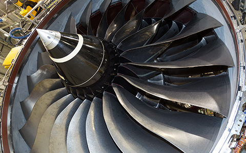
Anyone looking at a modern airliner from the front will first notice the fan. On current engines, it can exceed two meters in diameter and largely determines the outer dimensions of the nacelle. Its size is no side effect, but the expression of a fundamental design principle: a modern turbofan generates a substantial part of its thrust by accelerating a large mass of air by a relatively modest amount.
This sets the turbofan apart from the classic turbojet, in which almost all incoming air passes through the engine core before leaving at high velocity. In a turbofan, the airflow is already divided in the forward section of the aircraft engine.
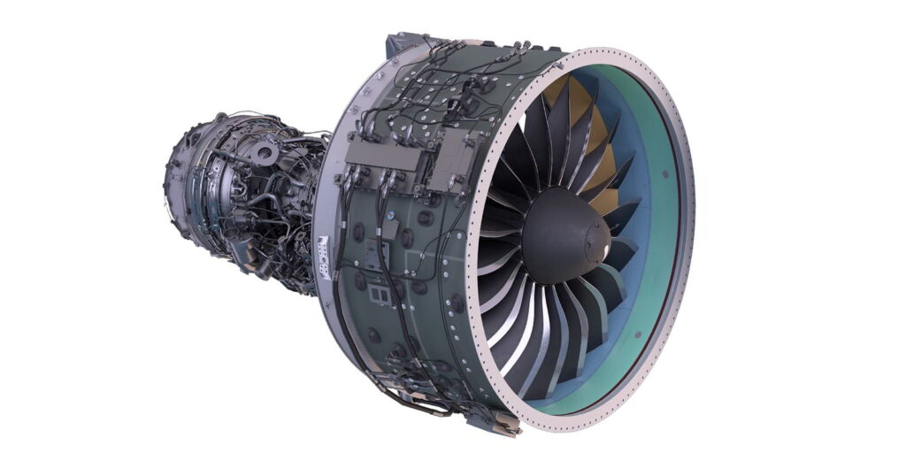
The fan splits the airflow into two paths
After entering the nacelle, the air first reaches the fan. Its rotating blades accelerate the entire incoming airflow.
Immediately downstream, the flow divides into two paths. The primary, or core, flow enters the inner part of the engine. The much larger secondary, or bypass, flow is routed around the gas generator. The ratio between these two mass flows is known as the bypass ratio. The higher the value, the more air flows around the engine core.
Modern civil turbofans have significantly higher bypass ratios than earlier generations. The PW1100G-JM from Pratt & Whitney’s GTF family, for example, has a bypass ratio of about 12:1. Put simply, for every kilogram of air flowing through the core, roughly twelve kilograms are routed around it.
This large bypass flow is one of the main reasons modern commercial aircraft engines are so efficient. To generate a given amount of thrust, it is more energy-efficient to accelerate a large mass of air by a relatively small velocity increment than to accelerate a small mass of air to an extremely high speed.
That is one of the key differences between early jet engines and today’s high-bypass turbofans.
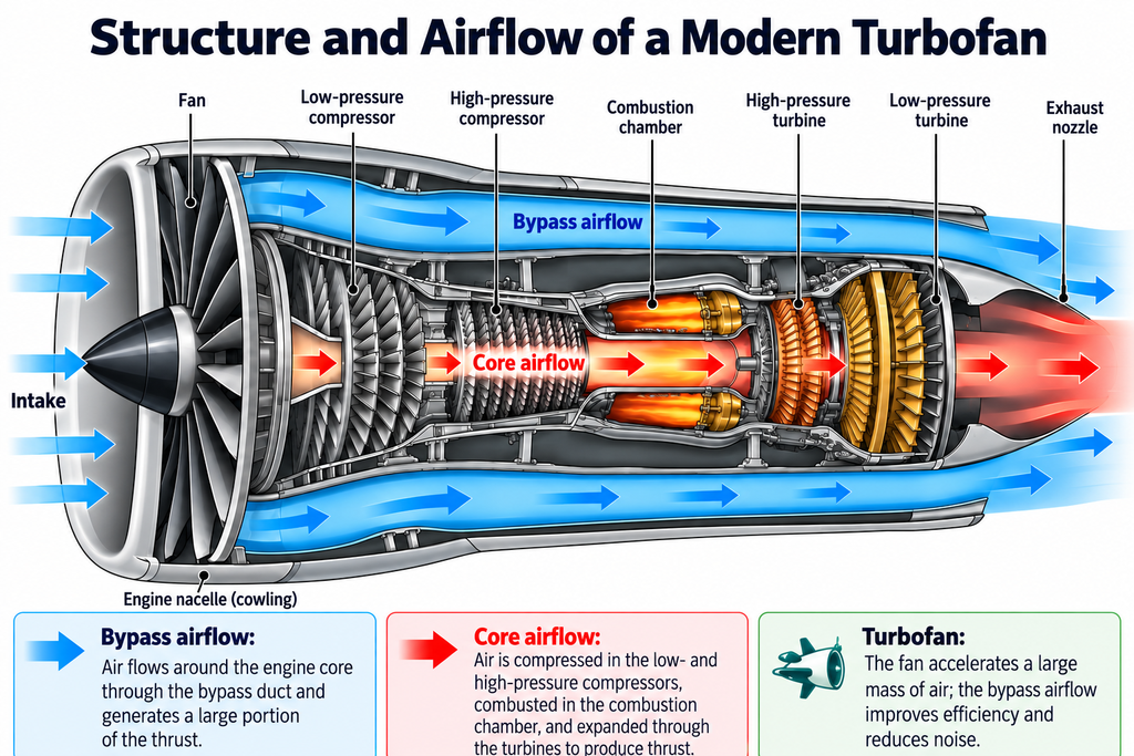
The gas-turbine process takes place in the core
Only part of the incoming air enters the engine core behind the fan. This is where the thermodynamic process begins that provides the energy to power the entire engine. The air is first compressed in several consecutive compressor stages.
Each stage consists of rotating and stationary rows of blades. The rotors add energy to the airflow, while the stators downstream redirect it and convert part of the flow velocity into pressure. Compression takes place progressively, with pressure and temperature increasing from stage to stage.
In a conventional two-spool engine, the low-pressure and high-pressure compressors are separated. Together with the combustor and high-pressure turbine, the high-pressure compressor forms the actual engine core and handles the final, particularly intensive stages of compression. By the time the air leaves the compressor, its volume has been reduced to a fraction of its original value, while pressure and temperature have risen substantially.
This creates the conditions required to burn the injected fuel efficiently and release the energy needed by the engine.
The combustor adds energy to the gas flow
The combustor is the energetic center of the engine. Fuel is injected into the highly compressed air and burned continuously. Unlike in a piston engine, the individual process steps do not occur one after another in the same chamber.
While fresh air is constantly being drawn in and compressed in the forward part of the engine, combustion continues in the combustor as hot gases farther downstream are already expanding through the turbines. The engine therefore operates as a continuous process.
The demands on the combustor are considerable. It must maintain stable combustion, keep pressure losses as low as possible and ensure that the temperature distribution at the turbine inlet is as uniform as possible. For this reason, only part of the air supplied by the compressor is used directly for combustion. A significant portion is used to cool components and to stabilize and mix the gas flow.
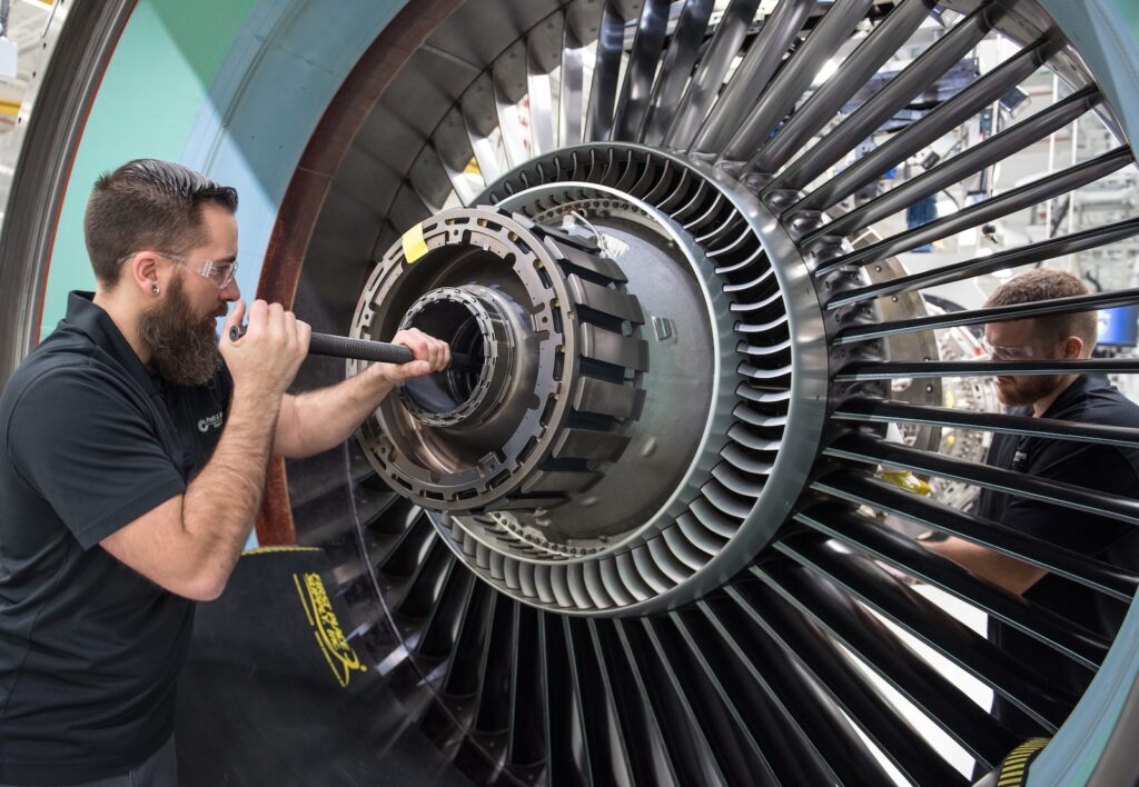
At the combustor exit, the working gas reaches its highest temperature anywhere in the engine. This is where the high-pressure turbine begins, one of the most technically demanding sections of the propulsion system, whose components must withstand extreme thermal and mechanical loads over long periods.
The turbine provides the mechanical power
The role of the turbine is often underestimated when looking at an aircraft engine. Its primary task is not to generate additional thrust, but to drive the components that make the working process in the forward section of the engine possible. The hot combustion gases first pass through stationary turbine vanes and then through the rotating turbine blades.
In the process, the turbine extracts part of the energy from the gas flow and converts it into rotational motion, which is transmitted forward through shafts.
In a conventional two-spool engine, power is transmitted through two independent shaft systems. The high-pressure turbine supplies the high-pressure compressor through the high-pressure shaft, while the low-pressure turbine farther downstream drives the low-pressure compressor and fan through a second, concentric shaft.
This creates a closed mechanical cycle: combustion adds energy to the gas flow, the turbines recover part of that energy and transfer it to the compressor stages and fan. This interaction means that once the engine has been started, it no longer requires an external drive and can effectively keep itself running.
Two spools – or three
An engine is divided into several spool systems mainly because the individual components achieve their highest efficiency at different rotational speeds. The large fan has to rotate comparatively slowly because of its diameter, limiting tip speeds, while the much smaller high-pressure compressor operates most efficiently at significantly higher rpm.
The two components therefore cannot be driven by the same shaft.
Many modern engines use the conventional two-spool layout. Rolls-Royce takes a different approach with its large Trent engines. An intermediate-pressure system, with its own compressor, turbine and shaft, is added between the low- and high-pressure systems. The three concentric shafts allow each turbine to drive exactly the compressor — or fan — assigned to it.
This makes it possible to tailor the respective speed ranges more precisely to the aerodynamic requirements of the individual components, improving overall system efficiency and giving engineers more freedom in the engine design.
The Geared Turbofan adds a gearbox
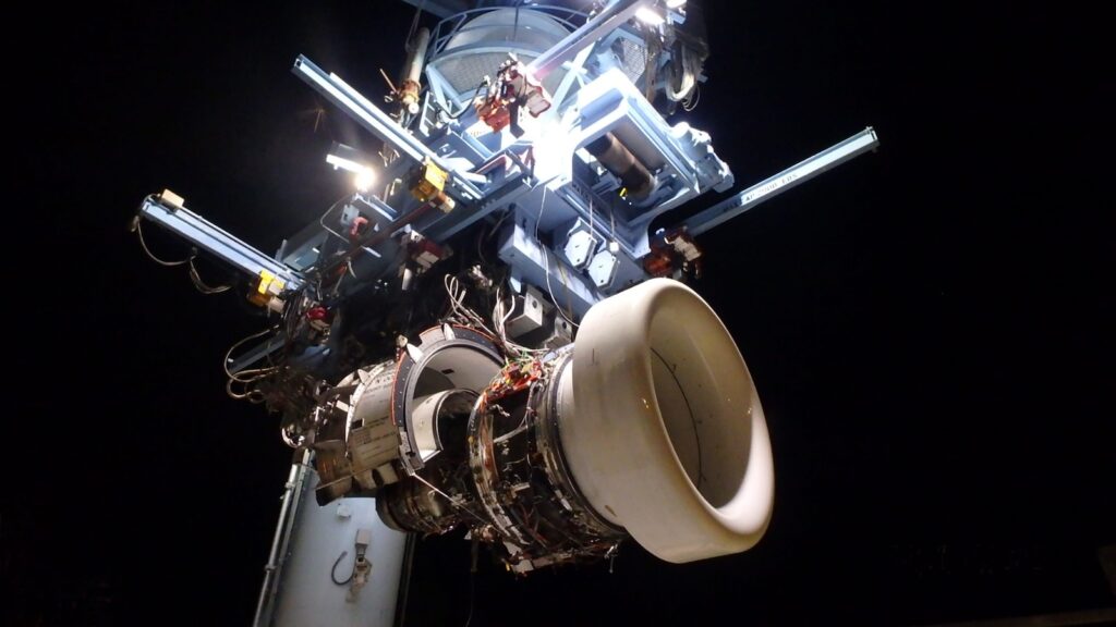
Pratt & Whitney follows a different approach to resolving the speed conflict between fan and low-pressure turbine with the Geared Turbofan. In a conventional turbofan, the fan and low-pressure turbine are directly connected through the low-pressure shaft and therefore rotate at the same speed. That represents a compromise: the fan favors lower rotational speeds for efficient operation, while the low-pressure turbine could deliver its power more effectively at higher speeds.
To allow both components to operate closer to their respective optimum, Pratt & Whitney integrates a reduction gearbox between the fan and low-pressure system. The mechanical connection remains intact, but the fan and turbine can run at different rotational speeds. This enables more efficient engine operation and creates additional flexibility in the overall architecture.
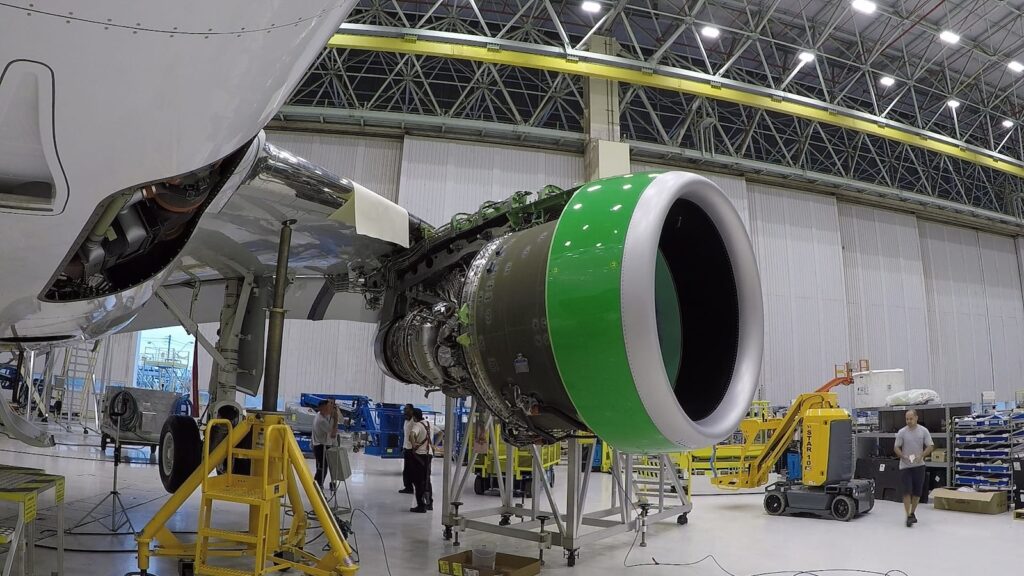
This principle underpins the GTF family, which is used, among other applications, on the Airbus A321neo. Pratt & Whitney has since further developed the architecture with the GTF Advantage. The gearbox does not alter the underlying thermodynamic process. Compressor, combustor and turbine continue to operate according to the same basic principles; what changes is the mechanical coupling between the low-pressure turbine and the fan.
Thrust comes from both the bypass flow and the core flow
At the end of the process, two air or gas streams leave the engine. The bypass flow has been accelerated by the fan and passes around the engine core. The core flow has also passed through the compressors, combustor and turbines. Both contribute to thrust. In physical terms, thrust results from the change in momentum of the air mass flowing through the engine: the engine takes in air at a certain velocity and expels it rearward with greater momentum.
The resulting force acts in the opposite direction.
The relative contributions of bypass and core flow depend on the specific engine architecture and operating condition. Blanket statements such as “80 percent of the thrust comes from the fan” are therefore problematic. What is clear, however, is that as bypass ratio increases, the fan becomes increasingly important to thrust generation. The core nevertheless remains indispensable because it provides the mechanical power required to drive the fan in the first place.
Why modern turbofans keep getting larger
The development of commercial aircraft engines over recent decades shows a clear trend toward larger fans and higher bypass ratios. From an engineering standpoint, the direction is understandable: a larger fan can move more air and thereby improve propulsive efficiency. There are limits, however.
Larger fans require larger nacelles, increasing mass and frontal area. Integration under the wing becomes more difficult, and ground clearance becomes a key design factor, particularly on narrow-body aircraft. At the same time, the engine core must continue to evolve. A larger fan requires more power, while the core itself is expected to remain compact and achieve high thermal efficiency.
Modern engine development therefore involves a careful balance between fan diameter, bypass ratio, pressure ratio, turbine temperature, weight, noise and installation space.
The next stage of development could shift that balance again. Concepts such as the Open Fan dispense with the conventional fan nacelle and target even larger effective bypass ratios. Airbus and CFM plan to flight-test the corresponding RISE technology on an A380 test aircraft toward the end of the 2020s.
Images: Pratt & Whitney, Rolls-Royce