
Translation note: This article was translated with the assistance of AI.
From simple piston engines and enormous radial engines to modern turbofans, the evolution of aircraft propulsion is a story of technological innovation. For more than a century, engineers have sought ways to increase power output, reduce fuel consumption, and make aircraft faster and more economical to operate. These efforts have produced fundamentally different propulsion concepts, some of which continue to rely on the same engineering principles today.
A journey through the history of aircraft propulsion.
The Beginnings: An Internal Combustion Engine Takes Humans into the Air
When the Wright brothers completed the first controlled, powered flight of an airplane with their Flyer I on December 17, 1903, they had just 12 horsepower at their disposal. The power came from a four-cylinder inline engine built in-house by their employee and mechanic, Charlie Taylor, at the brothers’ bicycle workshop. It was their third business venture, following a printing business and a bicycle repair shop.
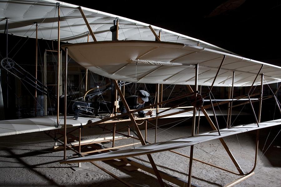
The Wright brothers’ four-cylinder engine drove two counter-rotating pusher propellers through a chain transmission. This basic principle remains in use today: An engine supplies mechanical power, which a propeller converts into thrust.
Aerodynamically, a propeller operates much like an aircraft wing. As its airfoil-shaped blades rotate, they create a pressure distribution that generates an axial force. In the process, air is accelerated rearward, producing a reaction force that propels the aircraft forward.
The Wright brothers had already recognized that a propeller’s aerodynamic design determines its efficiency. Their blades incorporated a twist along the span to account for the different rotational speeds at the blade root and tip.
This principle remained largely unchanged over the following decades, even as aircraft engines continued to evolve.
The Reciprocating Piston Engine: Mechanical Power from Individual Cylinders
Until the beginning of the jet age, reciprocating piston engines dominated aircraft propulsion. They convert the chemical energy stored in fuel into mechanical work through combustion.
In a conventional four-stroke spark-ignition engine, each cylinder completes four strokes: intake, compression, power, and exhaust. A spark plug ignites the compressed fuel-air mixture, generating pressure that pushes the piston downward during the power stroke. A connecting rod transfers this motion to the crankshaft, which drives the propeller.
Thermal efficiency depends on several factors, including compression ratio, combustion characteristics, heat losses, and mechanical friction.
Aircraft engines must deliver reliable power over extended periods. While an automotive engine frequently operates at only a fraction of its maximum output, an aircraft engine operates under high loads, particularly during climb.
The Horizontally Opposed Engine: Compact and Relatively Lightweight
An example of a modern aircraft piston engine is the Lycoming IO-360, used in the Cessna 172S. This air-cooled four-cylinder engine has a displacement of approximately 5.9 liters and produces 180 horsepower. Its cylinders are arranged horizontally opposite one another, allowing for a compact design with a relatively small frontal area and favorable engine balance.
In the Cessna 172S, the propeller is mounted directly to the crankshaft’s output end. No reduction gearbox is required.
Relatively simple piston engines are cost-effective in lower power classes and can achieve good fuel efficiency under suitable operating conditions. However, their power output is limited. As cylinder counts increase, so do weight, mechanical complexity, and cooling requirements.
The Era of Radial Engines: Increasing Power for Larger Aircraft
Commercial aviation expanded rapidly during the 1930s. Airlines needed larger aircraft with greater payload capacities, longer ranges, and better performance. Powerful radial engines provided the necessary propulsion.
In a radial engine, multiple cylinders are arranged radially around a central crankshaft. Their axes point outward in a star-shaped configuration, giving the engine its distinctive appearance and name. This arrangement allows a relatively large number of cylinders to be accommodated in a compact design.
A key engineering feature is the connecting-rod assembly. In a typical single-row radial engine, one piston is connected directly to the crankpin through a master connecting rod. The remaining pistons transmit their forces through articulated rods attached to the master rod assembly. This allows all cylinders in a row to drive the same crank mechanism.
Radial engines were generally air-cooled because their radially arranged cylinders were naturally exposed to the cooling airflow.
Pratt & Whitney R-1830: 14 Cylinders and 30 Liters of Displacement
One of the best-known radial engines is the Pratt & Whitney R-1830 Twin Wasp. Its 14 cylinders are arranged in two rows of seven cylinders each. The engine has a displacement of approximately 30 liters and, depending on the version, produced between 1,000 and 1,350 horsepower.
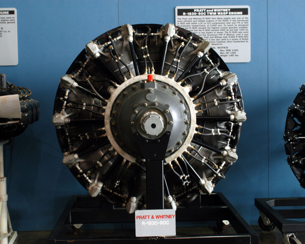
The R-1830 powered several versions of the Douglas DC-3. The aircraft first flew in 1935 and revolutionized passenger transportation, eventually becoming one of the most important commercial aircraft in aviation history. The DC-3 was powered by two radial engines and could carry 21 passengers in a common configuration.
The DC-3 helped establish passenger air transportation as an economically viable business in its own right. Improved reliability, better aerodynamics, and more powerful engines enabled significantly more efficient airline operations.
Radial Engines with 28 Cylinders
Following World War II, the development of large aircraft piston engines reached its peak.
One example was the Pratt & Whitney R-4360 Wasp Major. Its 28 cylinders were distributed across four radial rows. The engine had a displacement of approximately 71.5 liters and produced more than 3,000 horsepower in some versions.
Achieving this power output required considerable engineering effort. Supercharging, cooling, lubrication, and mechanical power transmission became increasingly complex.
Other large postwar aircraft engines, including the Wright R-3350, enabled the development of advanced long-range aircraft such as the Lockheed Constellation and Douglas DC-7.
For airlines, these aircraft offered higher speeds and greater range. At the same time, their sophisticated engines resulted in substantial maintenance costs. Further increases in piston engine power increasingly encountered economic and technical limitations.
The Gas Turbine Transforms Aviation
Alongside the continued development of piston engines, a fundamentally different propulsion concept emerged: the gas turbine.
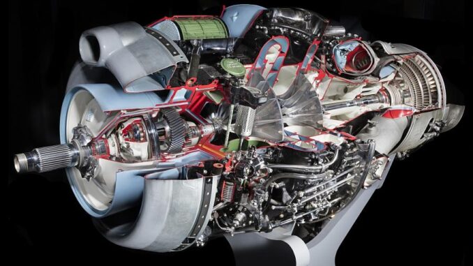
Unlike a reciprocating piston engine, a gas turbine operates through a continuous-flow process. Air enters the engine and is compressed. It then flows into a combustion chamber, where fuel is burned continuously. The hot combustion gases expand through a turbine, transferring part of their energy to the turbine rotor. The turbine drives the compressor through a shaft.
Gas turbines can deliver high power output with a relatively low weight, eliminate the need for reciprocating pistons, and process large mass flows of air.
The energy contained in the hot combustion gases can be used for propulsion in different ways, leading to the development of several distinct engine concepts.
The Vickers Viscount: Turboprop Propulsion Enters Airline Service
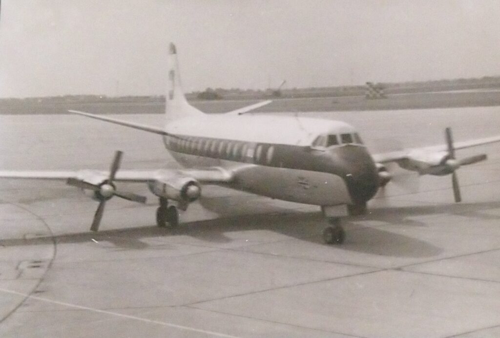

The British Vickers Viscount became the first turboprop-powered airliner to establish itself in regular passenger service. The prototype made its first flight on July 16, 1948. In 1953, British European Airways (BEA) introduced the Vickers Viscount 701 into scheduled airline operations.
Unlike the powerful radial engines used in contemporary airliners, its four Rolls-Royce Dart engines had no pistons or cylinders.
Rolls-Royce Dart: A Gas Turbine Driving a Propeller
The Rolls-Royce Dart was a turboprop engine featuring a two-stage centrifugal compressor and a multistage turbine. The compressor and propeller drive were mechanically coupled.
The turbine supplied power to both the compressor and, through a reduction gearbox, the propeller. Unlike many modern turboprops equipped with a free power turbine, the Dart did not separate the compressor and propeller drive into two mechanically independent turbine systems.
Early Viscount 701 aircraft were equipped with four Rolls-Royce Dart RDa.3 Mk 505 engines. Later versions of the Dart family achieved substantially higher power outputs.
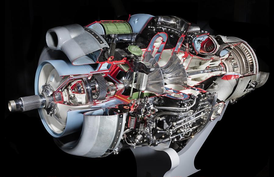
For passengers, the new propulsion technology offered noticeable advantages. The continuously rotating components of a gas turbine generated less of the mechanical vibration characteristic of large reciprocating piston engines. Advances in cabin design and passenger comfort provided further improvements.
The Viscount also proved commercially successful. Its combination of gas turbine propulsion, good cruise performance, and a design suited to regional airline operations made it attractive to numerous carriers. A total of 444 aircraft were built.
The Viscount demonstrated that gas turbines could serve as powerful mechanical drive systems for propellers. This principle remains the foundation of modern turboprop aircraft such as the ATR 72.
The Turbojet: Thrust from a High-Velocity Exhaust Stream
Early jet engines developed during World War II used gas turbine energy directly to generate thrust.
In a turbojet, incoming air is compressed before fuel is injected and burned. Part of the resulting energy drives the compressor through the turbine. The remaining energy is used in a propelling nozzle to accelerate the exhaust gases to high velocities.
The change in momentum of the gas flowing through the engine produces thrust. A turbojet therefore requires no propeller. Propulsion is generated primarily by the high-velocity exhaust jet.
This concept enabled flight speeds that were difficult to achieve with conventional propeller-driven aircraft. Early turbojet-powered airliners included the de Havilland Comet and initial versions of the Boeing 707.
At typical subsonic flight speeds, however, accelerating a relatively small mass of air to a very high velocity is energetically inefficient. A substantial portion of the supplied energy remains as kinetic energy in the exhaust stream rather than being converted into useful propulsive power.
This limitation helped drive the development of more efficient jet engines.
The Turboprop: A Gas Turbine Drives the Propeller
In a turboprop engine, much of the available energy is converted into shaft power through turbine stages. This power drives a propeller, which generates most of the thrust.
A turboprop therefore combines the thermodynamic operating cycle of a gas turbine with the aerodynamic working principle of a propeller.
How Does a Turboprop Work?
As in other gas turbine engines, incoming air passes through a compressor and combustion chamber. The hot combustion gases then drive turbine stages.
Many modern turboprops use a free power turbine. This turbine is not mechanically coupled to the compressor and can therefore rotate at a different speed.
Its power is transmitted to the propeller through a shaft and reduction gearbox. The gearbox is necessary because gas turbines can operate efficiently at high rotational speeds, while large propellers require comparatively low rotational speeds due to blade-tip speed limitations.
A well-known example of a turboprop featuring a free power turbine is the Pratt & Whitney Canada PT6, which powers aircraft including the Pilatus PC-12.
Why Are Turboprops Particularly Efficient?
The high propulsive efficiency of a propeller results from the large mass flow of air it moves.
Because of its relatively large diameter, a propeller acts on a substantial volume of air, accelerating it rearward. According to the principle of conservation of momentum, the thrust generated depends on the mass flow rate and the change in airflow velocity.
With a large mass flow, a relatively small increase in airflow velocity is sufficient to produce the required thrust.
As a result, less energy remains unused in the downstream airflow, improving propulsive efficiency.
This is particularly advantageous at low and medium flight speeds, where turboprops can achieve very high propulsive efficiency under suitable operating conditions.
Why Do Turboprops Fly Slower Than Turbofans?
The flight speed of a propeller-driven aircraft cannot be increased indefinitely without reducing propeller efficiency.
The reason lies in blade velocity. As a propeller rotates, its blades already move rapidly through the air, particularly near their tips. As aircraft speed increases, so does the relative airflow velocity experienced by the propeller blades.
This can lead to local supersonic flow and shock waves near the blade tips. These effects increase aerodynamic drag, create additional losses, and reduce propeller efficiency.
Modern propellers with optimized airfoil sections and swept blade tips can reduce these effects. Nevertheless, conventional turboprop aircraft are generally designed for lower cruise speeds than modern turbofan-powered airliners.
On regional routes, turboprops can offer economic advantages when their lower fuel consumption compensates for reduced cruise speed. One example is the ATR 72, powered by two turboprop engines.
The Turbofan: The Propeller Principle Inside a Duct
One of the defining features of a turbofan engine is the large fan at the engine inlet. Aerodynamically, it resembles a multibladed propeller, but operates inside a duct.
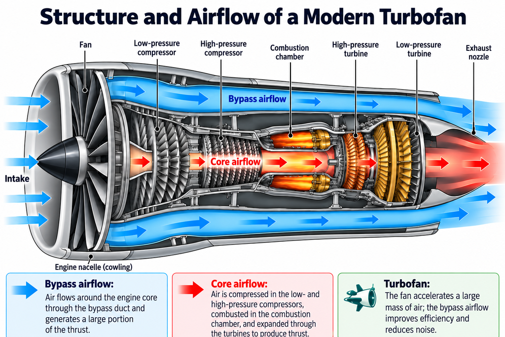
Part of the air entering the engine passes through the engine core. There, it undergoes further compression before fuel is added and burned.
The remaining airflow bypasses the core through a surrounding duct. This bypass air, accelerated by the fan, makes a major contribution to thrust generation.
In modern high-bypass-ratio commercial aircraft engines, the bypass stream produces a large proportion of total thrust.
The turbofan therefore exploits the same physical principle as a propeller: accelerating a large mass of air by a comparatively small amount.
The Bypass Ratio
The bypass ratio describes the relationship between the mass flow rate of air bypassing the engine core and the mass flow rate passing through it.
A bypass ratio of 10:1, for example, means that the bypass airflow has ten times the mass flow rate of the core airflow.
Increasing the bypass ratio can improve propulsive efficiency under suitable conditions. However, higher bypass ratios generally require larger fans.
This increases engine diameter, weight, and nacelle drag, among other factors.
Engineers developing modern turbofans must therefore balance aerodynamic efficiency against weight, installation space, and other engineering requirements.
The Geared Turbofan Resolves a Rotational Speed Conflict
In a conventional turbofan, the fan and low-pressure turbine are directly connected through a common shaft and rotate at the same speed.
Although mechanically straightforward, this arrangement requires a compromise. A large fan often operates most efficiently at relatively low rotational speeds, while the low-pressure turbine can be designed more efficiently for higher speeds.
Pratt & Whitney addresses this challenge in its Geared Turbofan architecture by placing a reduction gearbox between the fan and the low-pressure spool.
This allows the two components to operate at different speeds: The fan can rotate more slowly while the turbine operates at a higher speed.
The principle is similar to that of a turboprop, which also uses a gearbox between the turbine and propeller.
Comparison: What Are the Advantages of Different Aircraft Engines?
The pursuit of greater efficiency has been a major driver of aircraft propulsion development.
However, efficiency is not a single, universally interchangeable measure. A distinction must be made between thermal efficiency, propulsive efficiency, and overall efficiency.
Thermal efficiency describes how effectively the energy contained in fuel is converted into useful energy by the engine’s thermodynamic process.
Propulsive efficiency indicates what proportion of the energy made available for propulsion is converted into useful propulsive power.
Overall efficiency accounts for both factors.
A highly efficient powerplant does not necessarily result in the most efficient aircraft propulsion system. What matters is the interaction between energy conversion and thrust generation.
Comparing the Main Aircraft Propulsion Concepts
Operating economics also depend on more than fuel consumption alone.
On a short regional route, a turboprop is often more economical than a faster jet airliner. On longer routes, however, higher cruise speeds become increasingly important.
Other considerations include acquisition costs, maintenance intervals, airport charges, seating capacity, and daily aircraft utilization.
Open Fan: The Next Stage of Development?
Over several decades, turbofan development has produced progressively larger fans and higher bypass ratios.
However, the fan duct imposes practical limits on fan diameter. Larger nacelles increase weight and aerodynamic drag. Integrating increasingly large engines beneath aircraft wings also becomes more challenging.
One potential solution is to eliminate the duct altogether.
This is the approach being pursued by CFM International through its RISE technology demonstration program.
One of the program’s central technologies is an open-fan architecture. Unlike a conventional turbofan, it features a large, unshrouded rotor.
The objective is to accelerate a particularly large mass flow of air and thereby improve propulsive efficiency. In appearance, the concept resembles a turboprop.
Aerodynamically and structurally, however, the open-fan concept is being developed to meet the requirements of modern commercial aircraft.
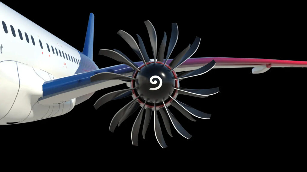
CFM is targeting flight speeds of up to Mach 0.8. This could allow an open-fan engine to operate in a speed range currently served predominantly by ducted turbofans.
Advanced Blade Geometries Enable Higher Speeds
The performance of an open fan depends particularly on rotor-blade aerodynamics and the management of transonic flow effects.
Modern three-dimensional blade profiles, blade sweep, and carefully controlled aerodynamic loading are intended to help limit losses and noise emissions.
The concept also presents demanding requirements for materials, structural strength, and aircraft integration.
An unshrouded rotor requires different engineering and safety assessments from a ducted fan, particularly regarding bird strikes, blade failure, vibration, and noise emissions.
Through the RISE program, CFM is targeting approximately 20 percent lower fuel consumption compared with today’s most efficient engines.
The intended improvement depends on several technologies, including the open fan and advances in engine-core design.
Further development work and flight testing will be needed to determine whether the targeted benefits can be fully realized in regular airline operations.
More Than 120 Years of Aircraft Propulsion: What Has Really Changed?
Looking at the development from the Wright Flyer to the open fan, two fundamental technological trends emerge.
The first concerns the conversion of chemical energy stored in fuel.
Early aircraft used relatively simple piston engines. Later, powerful radial engines enabled commercial long-distance air travel. The development of the gas turbine ultimately introduced a powerplant capable of delivering high power output with a favorable power-to-weight ratio.
The second trend concerns thrust generation.
A propeller accelerates a large mass of air by a comparatively small amount. Early turbojets, by contrast, relied on high-velocity exhaust streams.
As bypass ratios increased in modern turbofans, the efficient acceleration of large air masses once again became increasingly important.
The open fan could continue this development.
The history of aircraft propulsion therefore demonstrates that technological progress often builds on the refinement of well-established physical principles.
The propeller that enabled the Wright brothers to achieve powered flight in 1903 could, in a fundamentally evolved form, once again play a central role in a future generation of commercial aircraft.